01
Focused on Structural Members
Primarily checks linear structural members such as columns, beams, and braces, without mixing unrelated model information into the results.
First find corresponding beams, columns, and braces in two model files, then view differences in section, plan position, elevation, length, angle, and shape separately.
Useful for model version comparison, BIM vs. analysis model checks, architecture–structure coordination, and design-to-fabrication review. Whenever you need to know whether structural members in two model files are truly the same.
Data security note: uploaded model files and comparison results are processed temporarily and are generally removed within 24 hours.
StructMatch focuses on whether the geometry of beams, columns, and braces has changed.
Primarily checks linear structural members such as columns, beams, and braces, without mixing unrelated model information into the results.
Changes are separated into section, length, horizontal position, elevation, angle, and shape so you can see exactly what changed.
Property changes such as names, tags, and nonessential parameters are excluded from the difference results, keeping the review clear.
They can be different versions of the same model or models created by different teams or software. The goal is the same: check whether structural member geometry is consistent.
Who maintains the structural BIM model varies by workflow. Here are three common use cases.
The structural engineer maintains both the structural analysis model and the structural BIM model. Before issuing structural drawings, StructMatch can help check whether beams, columns, and braces in both models have been updated consistently.
When the structural engineer uses 2D CAD for structural drawings, the architect typically maintains the structural members in BIM. After a design change, the structural engineer usually updates the analysis model first. The architect can then use StructMatch to identify beam and column sections that need updating in BIM.
Once precise positions, such as beam offsets and lowered beams, have been coordinated, the revised architectural drawings are provided to the structural engineer for overlaying and updating the structural drawings.
Due to design schedules or other project needs, the architect and structural engineer may each maintain a separate BIM model containing structural members. After design changes, StructMatch can compare the two BIM models to check whether beam, column, and brace sizes and positions have been updated consistently.
A simple, traceable path from two model files to structural member difference results.
Choose IFC, ETABS (.e2k), SAP2000 (.s2k), or StructMatch (.smrevit) files.
Start with the short video to understand the basic workflow, then watch the full tutorial for detailed operation steps.
Things you may want to know before using the tool for the first time.
Supports IFC, ETABS (.e2k), SAP2000 (.s2k), and StructMatch (.smrevit) files. Exporting models as StructMatch files using the StructMatch Revit plugin can greatly improve comparison quality.
StructMatch is an structural model comparison tool focused on structural member geometry.
You can load two model files, and the system will try to find corresponding columns, beams, and braces, then check whether their section, length, horizontal position, elevation, angle, or shape is different.
It is not intended to list every changed property or parameter in the model. The goal is to narrow the result down to one question: did the structural member geometry change?
If you have two model files and what you actually care about is whether beams, columns, and braces are geometrically consistent, StructMatch is a good fit.
The system mainly reads two core pieces of information for each member: section and axis.
The section represents member size, such as RECT-500x800, BOX-300x300x12, or H-400x200x8x13.
The axis can be understood as the centerline along the member length. After extracting it, the system uses the axis to describe position, angle, shape, and length, together with other geometry information to find likely corresponding members. Once pairing is complete, section and geometry differences are checked item by item.
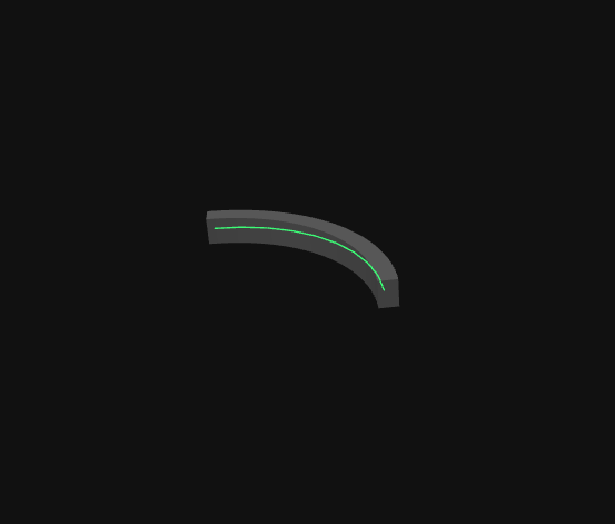
During pairing, the system uses each member in Model A as a reference and searches nearby for possible corresponding members in Model B.
If the two model coordinate systems are not aligned, corresponding beams or columns may be too far apart, causing the system to miss the correct pairing.
Therefore, when the two model origins or coordinates differ significantly, it is recommended to align the models first. The system can then search for corresponding members within a reasonable range and proceed with comparison.
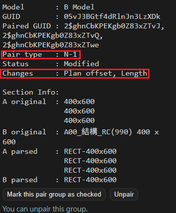
“Pairing” determines which member or members in Model B correspond to a member in Model A. Common pairing situations include:
“Comparison” checks whether paired members have differences, such as position, angle, section, shape, or length differences.
Simply put, pairing finds “which members belong together,” while comparison checks “whether there are differences within the pair.”
Ideally, the system can directly read each member’s section size from the IFC data.
In real projects, some members may be affected by joins, cuts, end trimming, conversion, or software-specific IFC export methods, making it difficult to infer the original section from geometry alone.
For example, a rectangular beam may be cut by columns, walls, or other elements at its ends, so its geometric shape is no longer a clean rectangle. In this case, geometry alone may not be enough to identify the correct section.
Section naming rules are used when geometry-based section detection is insufficient. The member name can then be used to specify the section size.
For example:
Automatic section naming detection: the system first attempts to find patterns in existing member names and apply possible section naming rules. Users can confirm, edit, or add rules to match project or company naming conventions.
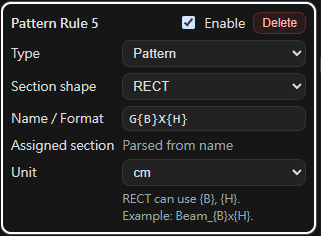
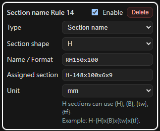
If the automatic result is not as expected, you can correct it based on the type of issue.
These features help the tool adapt to different company modeling habits, IFC export results from different software, and project-specific checking requirements.
Yes.
Users can adjust comparison items and certain tolerances based on project needs. For example, you can choose whether to compare position, angle, shape, section, or length, and adjust thresholds for position offset, angle difference, and length difference.
This is useful at different stages of model checking. During early coordination, you may only care about the section and position of major beams and columns. Before drawing issue or model delivery, you may use stricter tolerances for horizontal position, elevation, angle, and length.
The system temporarily processes uploaded model files and comparison results in order to complete the model comparison workflow.
The system regularly clears uploaded data and generated results. Temporary data is generally removed within 24 hours.
If you choose to provide IFC files through the feedback form and describe the issue you encountered, it will greatly help improve section parsing, pairing accuracy, and compatibility with IFC exports from different software.
I am the developer of StructMatch and a practicing structural engineer.
In my own work, I often do not need to know every BIM parameter that changed. I simply want to quickly confirm whether a beam or column section changed, whether a member moved, whether its elevation is consistent, or whether it was lengthened, shortened, or removed.
StructMatch therefore keeps the scope intentionally small and focuses on geometry comparison for structural members such as columns, beams, and braces. The two models can be different versions of the same project or come from different teams or software; using IFC, ETABS (.e2k), SAP2000 (.s2k), or .smrevit files exported with the Revit plugin, StructMatch uses the same workflow to turn them into visual structural difference results.
StructMatch is currently in Public Beta. If you have a real structural model comparison workflow, or encounter a case that cannot be parsed or paired correctly, feedback is very welcome.
This tool is an structural model comparison aid. Results are intended for design review and coordination reference only and should still be finally confirmed by qualified professionals.
The tool accepts IFC, ETABS (.e2k), SAP2000 (.s2k), and Revit-exported .smrevit files and focuses on beams, columns and braces. IFC exports may differ between software, and certain special geometry representations, Brep, Boolean clipping, or non-standard export contents may not be fully parsed.
Large models may require longer processing time. For best results, upload simplified model files that include only the beams, columns, braces, or other structural members you want to compare.
If you encounter any issues, have feedback, or are willing to share IFC test cases to help improve the tool, please contact: structmatch@gmail.com